Crossed roller bearings – Details
Crossed roller bearings – Overview
Product characteristics of crossed roller bearings
Product selection
Product series
Bearing-design
Installation-instructions
Tolerances
Suffix
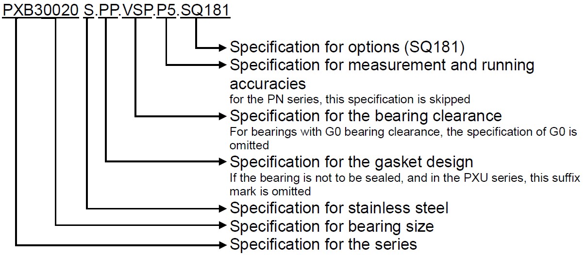
Structure of the order designation
Abreviation
Dimension tables
Crossed roller bearings – Overview
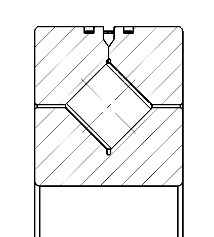
The performance of crossed roller bearings is outstanding compared to other slewing rings. Due to the crossed-roller arrangement of the cylindrical rollers they offer advantages such as:
- Assembly / Mounting
- Tilting moment
- Load capacity
- Rigidity
- Race Way Accuracy
These properties can be implemented in a single bearing location as a stand-alone solution, instead of the installation of a roller bearing combination to achieve a similar mechanical application. Therefore, it is a highly economical approach, based on the fact, that the effort and costs for the design of the connecting structure and the installation of multiple bearings are reduced.
The crossed-roller design enables:
- Carrying of radial loads
- Carrying of axial loads of both directions and
- Including of tilting moments and multiple load combinations
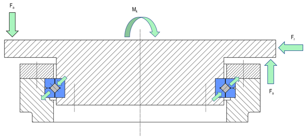
Carrying of external loads with crossed roller bearings
IBO crossed roller bearings are used as a bearing solution for a variety of applications:
- Machine tools
- Centrifuges
- Manipulators
- Hoists
- Luggage scanner
- Medical technology
- Antennas such as radar systems and telescopes
- ‘Out of the standard’ technology
- Automation, such as robot and handling systems
Product characteristics of crossed roller bearings
Running Characteristics
The enhanced running accuracy is achieved by designing high precision spacers for the cylindrical rollers. This exceptional designed guidance mechanism prevents skewing of the cylindrical rollers, which increases the running accuracy. Even with reduced or zero clearance (pre-tensioned preloaded inner and outer ring) the cylindrical rollers have no friction.
Rigidity
Due to the crossed-roller arrangement of the cylindrical rollers, the crossed roller bearing design can carry external loads from all directions. Compared to the combination of two angular contact ball bearings, the crossed roller bearings achieve a 3-4 times higher rigidity – with the same dimensions.
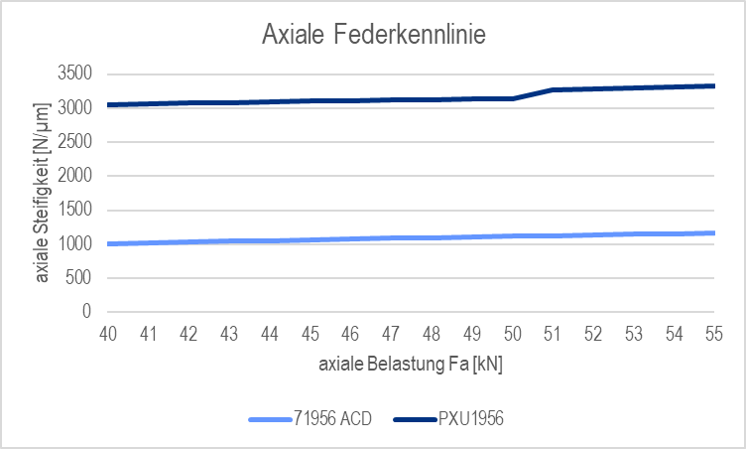
Comparison of the axial rigidity characteristics of crossed roller bearings and angular contact ball bearings
The width space requirement for crossed roller bearings is half as large as for angular contact ball bearings. Angular contact ball bearings can transmit tilting moments in an ‘O’- arrangement only.
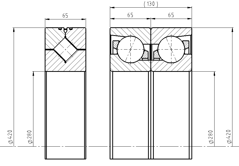
Comparison of the width of the bearing solution when transferring tilting moments
Load Capacity
Compared to conventional crossed roller bearings with sheet metal cages, the IBO crossed roller bearings have a significant higher load rating. This is possible by using spacers, which increase the contact lines (L1> L2). In addition, the spacers protect the track / raceway system by preventing the rollers from tilting. When using sheet metal cages, the rollers stay at the same place at the raceway and do not ‘circulate’.
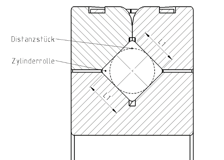
IBO crossed roller bearing with spacers and contact length L1
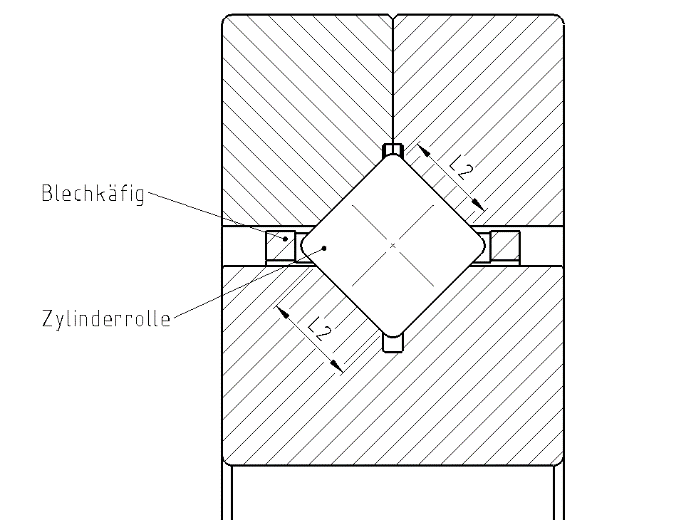
Crossed roller bearing with sheet metal cage and contact length L2
The spacers improve the load distribution and counteract the roller tilting. Roller tilting can significantly reduce the lifetime of a crossed roller bearing. When using sheet metal cages, the load zones in the inner and outer ring are asymmetrical (see the following illustration). The tilting moment acting on the track / raceway system increases with higher load. This can lead to an inclined position of the cylindrical rollers, which leads to an unevenly higher friction in the bearing and reduces the lifetime.
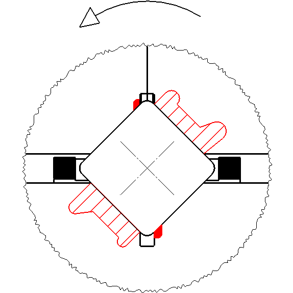
Symmetrical load distribution with IBO crossed roller bearings with the IBO spacer arrangement
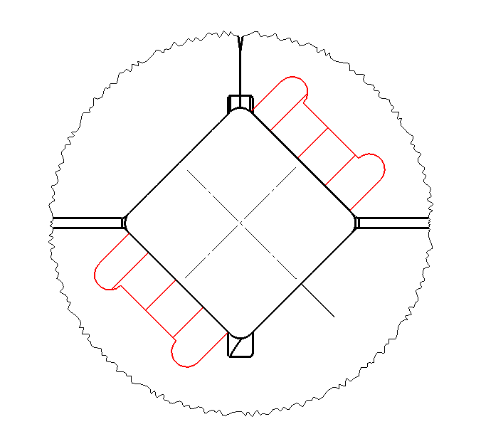
Asymmetrical load distribution for crossed roller bearings with sheet metal cages
Product selection
Operating temperature and the anticipated lifetime are key:
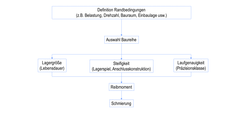
Procedure for the product selection with IBO crossed roller bearings
If the application requires certain materials for the bearing rings, such as corrosion-resistant stainless steels or aluminium materials (as a race system), we can manufacture this for you. Simply send us an inquiry using the contact form.
Lifetime Calculation
The lifetime for crossed roller bearings is calculated as follows:
For the lifetime calculation, application-specific criteria are considered by using the application factor fA. The values listed in the following table are assumptions for each application and the specific application criteria.
| Application | Requirement criteria | Application Factor fA |
|---|---|---|
| General Application | Smooth operation, without impact loads | 1.00 |
| General application | Operation with high shock loads | 3.00 |
| Automation | Rigidity | 1.25 |
| Radar System | Accuracy | 1.50 |
| Medical Technology | Smooth Running | 1.50 |
| Machine Tooling | Accuracy | 1.50 |
| Measuring Technology | Smooth Running | 2.00 |
The additional safety factor is defined with fS = 1 when there is no customer input. The standard situation does not need an additional safety factor to be included in the equation. There are exceptional cases, e.g. specifications approvals, internal factory regulations, requirement of audit firms. This must be communicated to IBO in advance and taken into consideration before the lifetime calculation.
The radial dynamic equivalent load is calculated as follows:
| Classification | X | Y |
|---|---|---|
 | 1.00 | 0.45 |
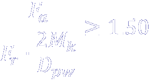 | 0.67 | 0.67 |
Static safety factor
If concussions (hefty vibrations) and or shock loads occur for a limited period, this must be considered as follows:
The additional safety factor is defined with fS = 1 when there is no customer input. The standard situation does not need an additional safety factor to be included in the equation. There are exceptional cases, e.g. specifications approvals, internal factory regulations, requirement of audit firms. This must be communicated to IBO in advance and taken into consideration before the lifetime calculation.
The radial dynamic equivalent load is calculated as follows:

| Type of the load | Static safety factor fstat |
|---|---|
| Normal load | 1.00 |
| Shock load | 0.67 |
Statically equivalent radial load
The permissible static axial load is calculated using the following formula:
Influences for the lifetime of crossed roller bearings
The lifetime of a crossed roller bearing is the actual time in utilisation. The lifetime can deviate significantly from the calculated nominal lifetime due to wear and / or fatigue. Possible causes are:
- Oscillating bearing movements with very small swivel angles (risk of false brinelling)
- Vibrations during downtime (stand still of the non-operating machine)
- Incorrect design or deformation of the connecting construction
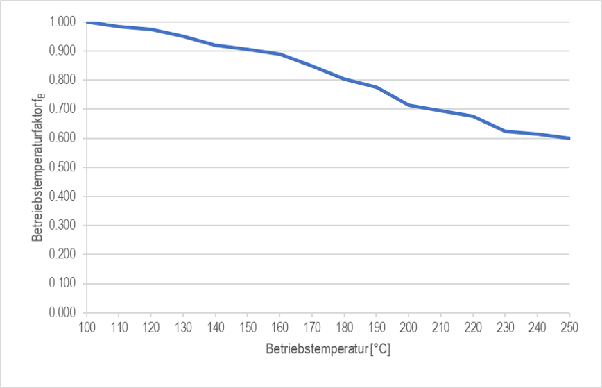
- Too high operating temperature
- Incorrect maintenance or lubrication
- Pollution
- Wrong mounting of the bearing
- Insufficient pre-tensioning / -loading of the fastening screws
Due to the variety of designs and the resulting installation and operating condition scenarios, the lifetime calculation is not a given real-world fact. With its’ mathematical formulas and algorithms built on real installation and operating conditions an approximate value, which is considered as a pretty accurate prediction of a roller bearing lifetime.
Product series
IBO manufactures crossed roller bearings of the PXU series according to the dimension series 10, 18 and 19 of DIN616. These correspond to the outer dimensions of the series of angular contact ball bearings 710, 718, 719, deep groove ball bearings 610, 618, 619 and cylindrical roller bearings N10, N18 and N19.
We also produce the PXB series. This is a very compact series and gives the user the opportunity to obtain a bearing solution, which is optimized for installation space in terms of concentricity (running accuracy) and rigidity.
The rings of the crossed roller bearings in the PXU and PXB series are standardised heat-stabilized for operating temperatures up to + 200 ° C (S1).
PXU series
Cross roller bearings of the PXU series are:
- Available in different versions regarding the dimensional- and running accuracy and the bearing (axial/radial) clearance as well
- Not sealed
- Greased when dispatched
Due to the outer ring split in the circumferential direction, this design is suitable for applications with a rotating inner ring.
In the standard version, the bearings are manufactured according to the tolerance class P0 which is given in WN001 and WN002. All bearing sizes mentioned in the dimension tables can be delivered up to a tolerance class P5. On request we are glad to offer dimensions, which are not listed in the dimension tables. Please contact us.
PXB series
Cross roller bearings of the PXU series are:
- Available in different versions regarding the dimensional- and running accuracy and the bearing (axial/radial) clearance as well
- Sealed
- Greased when dispatched
Due to the outer ring split in the circumferential direction, this design is suitable for applications with a rotating inner ring.
In the standard version, the bearings are manufactured according to the tolerance class P0 which is given in WN001 and WN002. All bearing sizes mentioned in the dimension tables can be delivered up to a tolerance class P5. On request we are glad to offer dimensions, which are not listed in the dimension tables. Please contact us.
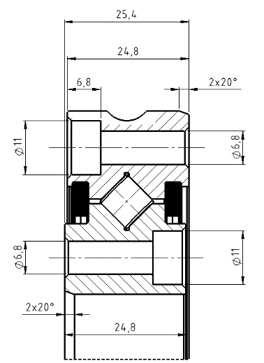
CRBSU08 series
Crossed roller bearings in the CRBSU08 series:
- Have a concentricity (running accuracy) of 0.01mm
- Are pre-loaded (zero or minus (axial/radial) bearing clearance)
- Are sealed on both sides
- Are lubricated at the factory with grease according to DIN 51825 KP2N 25
On request we offer dimensions, which are not listed in the dimension tables. Please contact us.
The CRBSU08 crossed roller bearings have two axial or radial grease nipples for relubrication according to the application. According to IT6, the inner- and outer diameter have attached centre markings for a precise adjustment (centring). The bearing rings can be installed directly to the connecting construction via the drilled-through holes in the inner and outer rings.
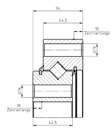
CRBSU14 series
Crossed roller bearings in the CRBSU08 series:
- have a concentricity (running accuracy) according to the information in the dimension tables
- are sealed on both sides and
- are lubricated at the factory with grease according to DIN 51825 KP2N 25.
On request we offer dimensions, which are not listed in the dimension tables. Please contact us.
There are 4 conical grease nipples on the outer diameter of the outer ring for relubrication during operation. According to IT7, the inner- and outer diameter have attached centre markings for a precise adjustment (centring). The bearing rings can be installed directly to the connecting construction via the drilled through-holes in the inner and outer rings.
Bearing design
PXU and PXB series
To utilize the advantages of crossed roller bearings, the connecting construction must be designed rigid accordingly. Crossed roller bearings are basically thin-walled. If the connecting construction, the housing, the mounting flange, or the mounting screws are not sufficiently designed, the bearing rings cannot carry load evenly. If there is no equally distributed contact between the cylindrical roller and the raceway system (here line contact), this can lead to deformations. This results in the reduction of the lifetime. Therefore, it is mandatory, to ensure an equal support in the circumferential direction and the height of the bearing ring as well (see the following figure).
The design of the connecting construction is explained in the following sub-items.
The design of the connecting construction is explained in the following sub-items.
Installation with a mounting flange
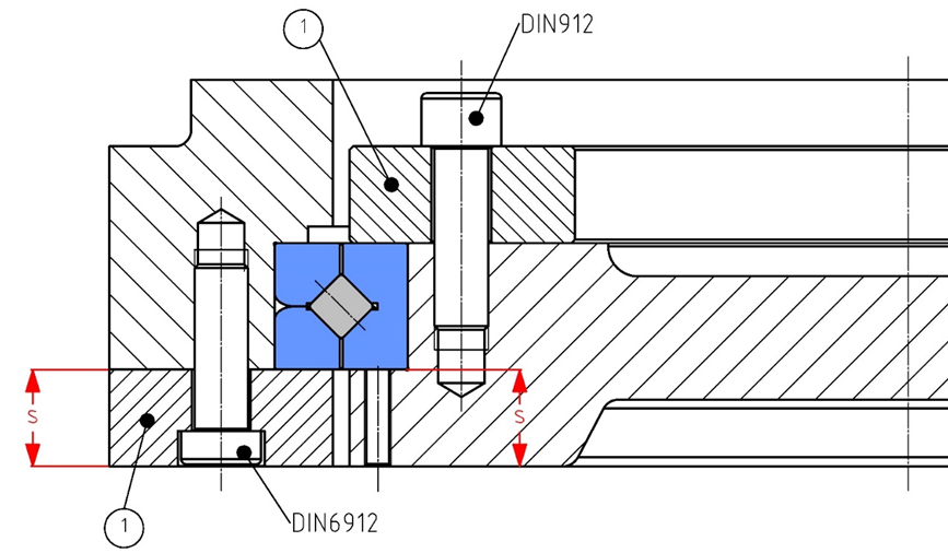
So-called mounting flanges are useful for attaching the crossed roller bearings PXU and PXB (see following illustration).
The minimum thickness S for the mounting flange as well as for the connection flange is determined as follows:
The through-holes and the counterbores are designed according to DIN 74, form J. Fixing screws according to DIN 6912. For deeper counterbores, the thickness of the clamping ring S must be increased by the amount of the additional countersink depth.
For screws of strength class 10.9, the minimum strength under the screw heads or nuts must be 500 N / mm2. No washers are required for these screws.
For fastening screws of strength class 12.9, the minimum strength must not be less than 850 N / mm2, or tempered washers must be used under the screw heads or nuts.
Depth of the bearing seat
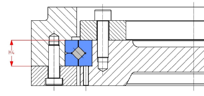
For the mounting flange to hold the bearing securely, the depth of the bearing seat t must be as shown in the following illustration.
The depth of the bearing seat influences the bearing clearance and the rotational resistance.
The bearing seat depth t is calculated as follows:
If there are special requirements regarding the rotational resistance, the depth t should be defined in correspondence with the respective height of the bearing ring. It has been proven and tested to use for the depth t the same or further narrowed tolerances as the dimension h in the dimension tables . However, for safety reasons your own tests should be carried out.
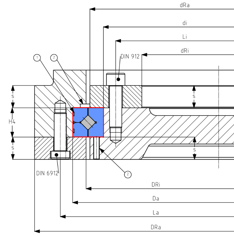
Note: number 2 in the figure above represents pull-off threads for a non-destructive dismounting possibility. At least 3 pull-off threads each must be provided for the inner and outer ring. No excessive force must be exerted on the bearing.
The nominal dimensions for the connecting construction are calculated as follows:


Note: The values for D Ri and d Ra in the sealed version of the PXB series differ from the above values. For details send your inquiry to Sales@IBO-Tec-China.com.
The following table shows the quantity and the size of the fastening screws:
| Outer diameter D From | Till | Quantity | Size |
|---|---|---|---|
| 100 | 200 | Minimum 12 | M4 – M8 |
| 200 | 500 | Minimum 16 | M5 – M12 |
| 500 | 1,250 | Minimum 24 | M12 – M16 |
The associated tightening torques are defined based on the VDI2230 and can be found in the table below:
| Mounting screw | Tightening torque |
|---|---|
| M5 | 9 |
| M6 | 14 |
| M8 | 30 |
| M10 | 70 |
| M12 | 120 |
| M16 | 200 |
Installation tolerances
For crossed roller bearings of the PXU series, the tolerance for the shafts are h7 and the housing bore is K7. If there are increased demands on running accuracy, then the shaft must be tolerated according to h6 and the housing bore according to K6.
In the PXB series with GX clearance, the tolerance for the shaft must be h5 and the housing bore is H7. In the case of G0-clearance, the shaft must be tolerated according to j5, the housing bore must also be defined according to H7. With normal clearance G0 and shock load or high tilting moments, the shaft tolerance must be k5 and the housing bore is J7.
For crossed roller bearings with preload: the preload can increase due to press fits, for this reason, press fits should be avoided with crossed roller bearings with preload. A transition fit with clearance “0” should be aimed for. For the mounting activity, as a service, we mark the deviation of the nominal dimensions for the inner Ø and outer Ø on the bearing ring. If this is required, it must be stated in the article description with SQ181.
Series CRBSU08 and CRBSU14
The bearing rings of the CRBSU series can be screwed directly into the connecting construction. No press or transition fit is required. To ensure a proper functioning of the crossed roller bearings, a rigid connecting construction is required. For a proper screw connection, a non-positively connection between the bearing rings and the connecting structure must be implemented.
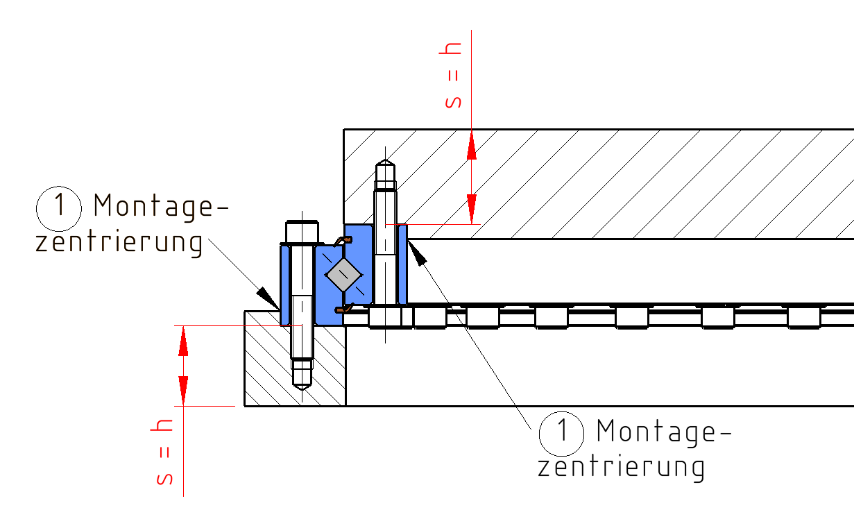
As shown in the figure below, the respective wall thickness s must be equal to h of the connecting construction. The individual ring heights can be found in the respective dimension table or the associated delivery drawing. Furthermore, the connecting construction must be dimensioned in a way, that the bearing rings are supported over the entire contact surfaces.
The mounting /assembly centring marks ease the assembly. The customer can implement this for a bearing ring or omit it entirely.
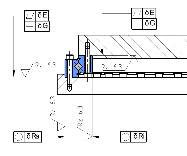
The specifications for the shape and the position tolerances of the connecting construction can be found in the table below:
Shape and position tolerances of the CRBSU connecting construction:
| Abbreviation | δE [mm] | δG [mm] | δRa [mm] | δRi [mm] |
|---|---|---|---|---|
| CRBSU080168 | 0.060 | 0.030 | 0.015 | 0.013 |
| CRBSU080188 | 0.060 | 0.030 | 0.015 | 0.013 |
| CRBSU080218 | 0.060 | 0.030 | 0.016 | 0.013 |
| CRBSU080258 | 0.060 | 0.030 | 0.016 | 0.015 |
| CRBSU080318 | 0.070 | 0.035 | 0.018 | 0.016 |
| CRBSU080398 | 0.070 | 0.035 | 0.020 | 0.018 |
| CRBSU140414 | 0.070 | 0.035 | 0.030 | 0.030 |
| CRBSU140544 | 0.080 | 0.040 | 0.035 | 0.030 |
| CRBSU140644 | 0.080 | 0.040 | 0.040 | 0.035 |
| CRBSU140744 | 0.090 | 0.045 | 0.045 | 0.040 |
| CRBSU140844 | 0.090 | 0.045 | 0.045 | 0.040 |
| CRBSU140944 | 0.100 | 0.050 | 0.055 | 0.045 |
| CRBSU141094 | 0.100 | 0.050 | 0.055 | 0.055 |
Installation instructions
PXU and PXB series
The split outer ring of the PXU series is held together by 3 tooth lock washers and must under no circumstances be subjected to tensile stress.
In practice, the following sequence for crossed roller bearings has proven to be useful:
At the start of the assembly all components must be cleaned and checked for burrs. The actual dimensions
- Housing bore Da
- Shaft diameter di
- Bearing seat height H4
must be documented before assembling the components.
For the next step, insert the crossed roller bearing into the housing bore and fix it with the associated mounting flange. Tighten the fastening screws crosswise according to the following illustration:

Installation of outer ring series PXU and PXB
- Gear ring
- Cross roller bearings
- Case
- Mounting flange
- Clamping bolt
The tightening to the nominal tightening torque takes place in 2 steps.
In the first step ‘Tan x 0.5’. Now turn the inner ring several times so that any tension in the bearing system is released.
In the next step, the shaft is mounted on the inner ring and the mounting flange for the inner ring is attached as shown in the figure below. It is important to ensure that the screws are tightened in the order shown:

Installation of outer ring series PXU and PXB
- Gear ring
- Connection construction inner ring
- Clamping ring inner ring
- Clamping bolt
It should be noted that the tightening to the nominal tightening torque of the fastening screws takes place in 3 – 4 steps and the inner ring must be turned several times in each step.
Series CRBSU08 and CRBSU14
At first, the outer ring is installed in the housing.
This can be done with the following steps:
- The crossed roller bearings are matched with the centring marks of the outer diameter in the connecting construction (housing) and align the bolt circle diameters of the outer ring and the housing to each other. If there is no centring used, the bolt circle diameter and the eye must be aligned concentrically.
- In the next step, the outer ring is fixed using the fastening screws including the washers. Here, the screws are tightened crosswise and the nominal tightening torque of the screws is tightened in 3 steps with even distribution to avoid a preload of the bearing rings.
- Turn the inner ring per tightening torque step: at least 50% of all screw pitches, one complete turn if possible.
- The nominal tightening torque can be found in the table “Tightening torques for fastening screws” above.
The assembly sequence of the inner ring is as follows:
- Position the associated connecting construction above the inner ring assembly centring and position the bolt circle diameter for the screw connection concentrically to each other. If no assembly centring is used, the bolt circle diameters must be aligned concentrically with each other using the eye.
- In the next step, the inner ring is fixed to the connecting construction using the fastening screws including the washers. Here, the screws are tightened crosswise and the nominal tightening torque of the screws is tightened in 3 steps with even distribution to avoid a preload of the bearing rings.
- Turn the inner ring per tightening torque step: at least 50% of all screw pitches, one complete turn if possible.
- The nominal tightening torque can be found in the table “Tightening torques for fastening screws” above.
- To check the assembly, the following criteria must be checked:
- Accuracy with dial gauge; Values according to the delivery drawing
- Rotational resistance: the rotational resistance installed is higher as in the delivery condition
- Storage temperature: after the distribution of grease, the bearing temperature must remain constant when the load and speed is constant
Tolerances
The running accuracies of the IBO crossed roller bearings are based on DIN620 and ISO492 and are summarized in WN001 .
In principle, crossed roller bearings can be manufactured within the accuracy classes PN, P6 and P5. Project-specific versions can be delivered in coordination with IBO. Please contact us.
Tolerances PXU Series
The tolerances for all dimensions of the PXU series, the inner diameter is K6 and outer diameter is h6. The installation height H and the height of a single ring are tolerated according to the following table:
Bore hole code | Bearing height H 1) Max. | Min. | Ring hight PXU18 h1) Max. | Min. | Ring hight PXU19 h1) Max. | Min. | Ring hight PXU10 h1) Max. | Min. |
|---|---|---|---|---|---|---|---|---|
| 20 | +0.12 | -0.12 | 0.000 | -0.01 | – | – | – | – |
| 24 | +0.12 | -0.12 | 0.000 | -0.01 | – | – | – | – |
| 28 | +0.12 | -0.12 | 0.000 | -0.01 | – | – | – | – |
| 32 | +0.12 | -0.12 | 0.000 | -0.025 | – | – | – | – |
| 36 | +0.13 | -0.13 | 0.000 | -0.025 | – | – | – | – |
| 40 | +0.13 | -0.13 | 0.000 | -0.025 | 0.000 | -0.05 | 0.000 | -0.075 |
| 44 | +0.13 | -0.13 | 0.000 | -0.025 | 0.000 | -0.05 | 0.000 | -0.075 |
| 48 | +0.13 | -0.13 | 0.000 | -0.025 | 0.000 | -0.05 | 0.000 | -0.075 |
| 52 | +0.13 | -0.13 | 0.000 | -0.025 | 0.000 | -0.05 | 0.000 | -0.075 |
| 56 | +0.13 | -0.13 | 0.000 | -0.025 | 0.000 | -0.05 | 0.000 | -0.075 |
| 60 | +0.14 | -0.14 | 0.000 | -0.05 | 0.000 | -0.75 | 0.000 | -0.1 |
| 64 | +0.14 | -0.14 | 0.000 | -0.05 | 0.000 | -0.75 | 0.000 | -0.1 |
| 68 | +0.14 | -0.14 | 0.000 | -0.05 | 0.000 | -0.75 | 0.000 | -0.1 |
| 72 | +0.14 | -0.14 | 0.000 | -0.05 | 0.000 | -0.75 | 0.000 | -0.1 |
| 76 | +0.14 | -0.14 | 0.000 | -0.05 | 0.000 | -0.75 | 0.000 | -0.1. |
| 80 | +0.15 | -0.15 | 0.000 | -0.05 | 0.000 | -0.75 | 0.000 | -0.1 |
| 84 | +0.15-0 | -0.15 | 0.000 | -0.05 | 0.000 | -0.75 | 0.000 | -0.1 |
| 88 | +0.15 | -0.15 | 0.000 | -0.05 | 0.000 | -0.75 | 0.000 | -0.1 |
| 92 | +0.15 | -0.15 | 0.000 | -0.05 | 0.000 | -0.75 | 0.000 | -0.1 |
| 96 | +0.15 | -0.15 | 0.000 | -0.05 | 0.000 | -0.75 | 0.000 | -0.1 |
| 500 | +0.16 | -0.16 | 0.000 | -0.05 | 0.000 | -0.75 | 0.000 | -0.1 |
| 530 | +0.16 | -0.16 | 0.000 | -0.05 | 0.000 | -0.75 | 0.000 | -0.1 |
| 560 | +0.16 | -0.16 | 0.000 | -0.05 | 0.000 | -0.75-0.05 | 0.000 | -0.1 |
| 600 | +0.16 | -0.16 | 0.000 | -0.05 | 0.000 | -0.75 | 0.000 | -0.1 |
| 630 | +0.18 | -0.18 | 0.000 | -0.075 | 0.000 | -0.1 | 0.000 | -0.125 |
| 670 | +0.18 | -0.18 | 0.000 | -0.075 | 0.000 | -0.1 | 0.000 | -0.125 |
| 710 | +0.18 | -0.18 | 0.000 | -0.075 | 0.000 | -0.1 | 0.000 | -0.125 |
| 750 | +0.18 | -0.18 | 0.000 | -0.075 | 0.000 | -0.1 | 0.000 | -0.125 |
Tolerances PXB Series
The dimensional accuracy tolerances for the inner diameter, outer diameter and the bearing height for the PXB series correspond to DIN620 and ISO492 and are summarized in the company standard WN001. Our customers can order bearings with dimensional accuracy according to PN and running accuracy according to P5. A possible article name (designation) could be PXB40040 PN5.
Suffix
| Suffix | Description | PXU-Series | PXB-Series |
|---|---|---|---|
| G0 | Normal clearance | X | X |
| GX | Reduced clearance | X | X |
| G1 | Increased clearance | X | |
| VSP | Preload | X | X |
| VSP.P5 | Preloaded and running accuracy P5 WN001 and WN002 | X | |
| P05 | Dimensional accuracy PN and running accuracy P5 | X | |
| P | Seal on one side only | X | |
| PP | Seal on both sides | X | |
| SN | Grease nippel | X | |
| S | Stainless steel version | X | X |
| SQ181 | Marks of the deviation from the nominal size of the inner Ø | X | X |
Structure of the order designation
Abbreviation
| Abbreviation | Description |
|---|---|
| Dpw | Running circle diameter of the rolling bearing |
| d | Inner diameter, inner ring |
| d1 | Rim diameter, inner ring |
| D | Outer diameter, outer ring |
| D1 | Rim diameter, outer ring |
| H | Height of the bearing |
| h | Height of the inner or outer ring |
| rmin | Minimal edge shortening (reduction) |
| K | Size of the 3 lubrication holes on the outer ring |
Dimension tables
You can access the dimension tables via the following links
There you can also download the CAD model for the respective crossed roller bearing.


